CLIP SYSTEM FOR SPORT
SPECIFIER'S INFORMATION
D 2.1
D 2.1
Fig. 1
D 1.0 General information
D 1.1 Clip Sports Information
D 2.1 Specifier's Information
D 2.1.1 Laying Instruction
GENERAL DESCRIPTION
Junckers Clip Sports Floor System is based on 22 mm solid boards laid as a floating floor with clips on a resilient foam underlay. The floor system is an area elastic type of sports floor with medium shock absorbency and elasticity particularly suitable for fitness and aerobics as well as in refurbishment projects.
The construction height is 27 mm or 32 mm, depending on the thickness of the foam underlay.
The floor system when 10 mm foam is used will conform to EN 14904:A3.
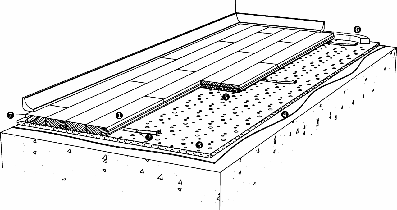
Please note that full documentation of a floor system comprises the data in D 1.0, D 1.1, 2.1 and D 2.1.1, see Figure 1.
FLOOR COMPONENTS - JUNCKERS CLIP SYSTEM
FLOOR COMPONENTS
1 - Floor boards
22 mm solid hardwood floor boards.
Wood species, dimensions, grades and finish, see B 2.0
Thickness x width x length
22 x 129 x 3700 mm
2 - Clips
Choice of clip size, see D 1.1
3 - Intermediate layer
5 mm Junckers SportsFoam
10 mm Junckers SportsFoam
See H 3.3
4 - Moisture barrier on concrete
0.20 mm PE membrane, e.g. Junckers Moisture Barrier
5 - Header joint adhesive
Junckers SylvaFix
6 - Junckers expansion strip
• 12 x 12 mm
7 - Expansion gap at the wall
2 mm per metre of floor width on each side, min. 30 mm.
Is also required at fixed points, e.g. columns.
Fig. 2

SYSTEM SPECIFICATIONS
The clip system is installed as a floating floor on a dry, load-bearing floor of concrete, lightweight concrete or wooden materials, e.g. an existing sports floor.
The subfloor must be flat with a maximum deviation of 2 mm under a 1.5 m straight edge (UK: 3mm under a 2 m straight edge). The surface must be smooth. Any minor irregularities must be corrected.
The choice of intermediate layer depends on the structure of the subfloor and the moisture conditions.
FLOOR BOARDS
Boards are laid in a continuous, irregular pattern, with header joints distributed randomly across the entire floor.
To avoid waste, the off cut from the last completed row can be used to start a following row.
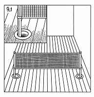
FLOOR ROSETTES
Floor rosettes must be mounted so that both vertical and horizontal movement of the floor is unimpeded.
The internal diameter of the flange must exceed that of the pipe, i.e. the external diameter of the net pole, by minimum 40 mm.
At the outer zones of the floor all flanges are mounted eccentrically towards the centre of the floor in relation to the bush fittings in the concrete, see Fig. 3.
Fig. 3

Fig. 4
POINTLOAD BEARING STRENGTH
The Clip Sports Floor System is tested and approved for below mentioned maximum point loads, in relation to load area:
Diameter, 25 mm: 3.5 kN ( 350 kg) 100x100 mm: 4.0 kN ( 400 kg)
LOAD-BEARING STRENGTH
The load-bearing strength of the clip system depends on the load, load area and subfloor type. The floor's total transverse expansion can also play a role, depending on the climate conditions in the hall and the clip size. Table 1 shows use of the floor system in relation to the load classes in EN 1991-1-1.
| Table 1 | Loading types | |
| Loading category | Area- and Point load | Wheel load |
| C4: Assembly halls for physical activity, e.g. gyms/theatres | Approved* | Approved** |
| C5: Assembly halls which can be crowded, e.g. sports halls incl. stands | Approved | Approved** |
*Point load area min. 200 x 200 mm
**Wheel loads, see D 1.0 - Table 2
See Fig. 4 for specific point load bearing strength.
For further definition of load classes and types, see D 1.0 - Stiffness and loadbearing strength.
CONSUMPTION OF MATERIALS
Net consumption for Clip Sports Floor System:
Boards: Area + approx. 2% wastage
Clips: 17 pcs. per m² Junckers
SportsFoam: Area + approx. 2% wastage
Junckers SylvaFix: 1 bottle per 75 m²
Junckers expansion strip: 2 x floor width
Moisture barrier (always on concrete): Area + approx. 10% wastage incl. overlaps
For halls with many columns, etc. extra clip consumption must be included in the estimated consumption.
